The PDP-12 is a dual-processor 12-bit minicomputer designed for interactive, real-time laboratory use. It was introduced in 1969 and 725 were built before the line was discontinued in 1972.

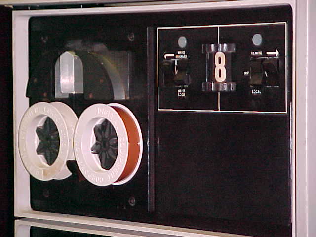
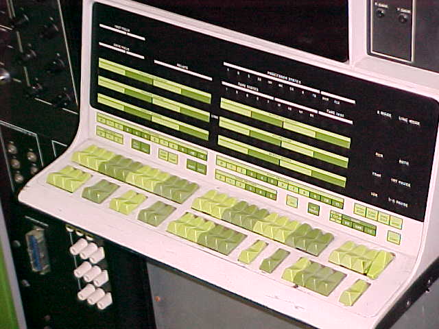
The basic machine came configured with dual LINCtape drives, a scope display, and IO ports for interfacing with external laboratory equipment.

It can run a number of different operating systems, including DIALPS, LAP6W, and OS/8.


Although you can program the PDP-12 from the front panel, it is normally used with a terminal attached for user interaction. Typically this would have been an ASR33 Teletype, but it could be any current loop or RS232 device.

Some software for the LINC line used the display scope on the PDP-12 for display, and only the input from the terminal keyboard.


Unlike most tape drives, linctape are random access read/write, so you can have a filesystem on tape and use it interactively like a disk.

The PDP-12 has special instructions for dealing with real world devices, since it was designed for lab use. Sampling an analogue input channel and putting the results in the accumulator is one instruction. Setting the relays is one instruction. Displaying a point on the scope is one instruction.

The external IO ports include eight analog input ports connected
to 1/4" jacks, six digital outputs connected to mechanical relays,
and a connector for an external oscilliscope:
There are eight analog input ports connected to dials, and a
speaker connected to the high bit of the accumulator:
There are also frequency triggers:


The PDP-12 has an awe-inspiring front panel. Two sets of twelve switches allow you to set address and data seperately for toggling in code, or for controlling a running program. Single instructions give access to either set of switches.

The displays and switches on the front panel are:

DISPLAY: INST FIELD - 5 bits
DATA FIELD - 5 bits
RELAYS - 6 bits
INSTRUCTION REGISTER - 12 bits
PROGRAM COUNTER - 12 bits
MEMORY ADDRESS - 12 bits
LINK
PROCESSOR STATES - 9 bits
TAPE STATES - 6 bits
TAPE INSTRUCTION - 3 bits
MULTIPLIER QUOTIENT - 12 bits
ACCUMULATOR - 12 bits
MEMORY BUFFER - 12 bits
8 MODE
LINC MODE
RUN
AUTO
TRAP
INTERRUPT PAUSE
ION
I/O PAUSE
SWITCHES: Left Switches (12)
Instruction Field (3)
Fill
Fill/Step
Exam
Exam/Step
Mark
Auto
Right Switches (12)
Sense (6)
Do
I/O Preset
Mode: LINC/8
Fetch Stop
Exec Stop
Single Step
Stop
Start 20
Start 400
Start Left Switches
Continue


The PDP-12's CPU is constructed out of a large number of small circuit boards ( flip chips ) each of which performs some very simple, generic function. The boards are connected together with a custom wire-wrapped backplane to impliment the architecture of the processor.

The PDP-12 has a large backplane broken into two sections:

There are 240 slots for flip-chips in each half of the backplane.

The basic PDP-12 configuration includes two 4K core stacks of 12-bit words. The core memory stacks can be seen inbetween rows of flip chips, a few rows down from the top, next to their W025 driver boards:

This is a list of all the flip chips used in the PDP-12 backplane.


Go to the RCS homepage.
Return to Dave's RCS page.
Return to Dave's homepage.